

 English
 Español
How to replace a fuel injector line?
Content
- 1 Common Types of Fuel Injector Lines and Their Characteristics
- 2 How Fuel Injector Lines Are Built: Material, Structure, and Working Principle
- 3 Application Scenarios and Key Selection Criteria for Fuel Injector Lines
- 4 Fuel Injector Line Types: Detailed Comparison
- 5 Replacement and Maintenance Guidance: How to Replace a Fuel Injector Line Safely
- 6 Frequently Asked Questions About Fuel Injector Line Replacement
- 6.1 What is the correct procedure for replacing a fuel injector line?
- 6.2 Do I need to relieve fuel system pressure before removing an injector line?
- 6.3 Can a fuel injector line be bent or reshaped during installation?
- 6.4 What torque should be used when installing a new fuel injector line?
- 6.5 How do I know if a fuel injector line needs to be replaced rather than repaired?
- 6.6 What should a workshop or wholesaler look for when sourcing replacement fuel injector lines from a manufacturer?
Replacing a fuel injector line involves five core steps: confirm the correct replacement line specification, relieve residual fuel system pressure, disconnect the old line at both the pump/common-rail end and the injector end using the correct size wrench, install the new line by hand before torquing the union nuts to the specified value, and check every connection for leaks after restarting the engine. Because a fuel injector line (also called a high-pressure fuel injection pipe) operates under extreme, rapidly cycling pressure, matching the exact pressure rating, diameter, length, and bend geometry of the original line matters far more than it does for most other automotive tubing. This guide walks through the common types of fuel injector lines, how they are built, where each type is used, a detailed comparison between line configurations, a full replacement and maintenance procedure, and answers to common questions, giving technicians, fleet operators, and parts buyers the practical detail needed to complete a safe, correct replacement.
Common Types of Fuel Injector Lines and Their Characteristics
Not every fuel injector line looks or performs the same way. The correct type depends on the fuel injection system it serves, the pressure it must withstand, and how much routing flexibility the engine bay allows. The cards below outline the configurations most commonly encountered when sourcing a replacement line.
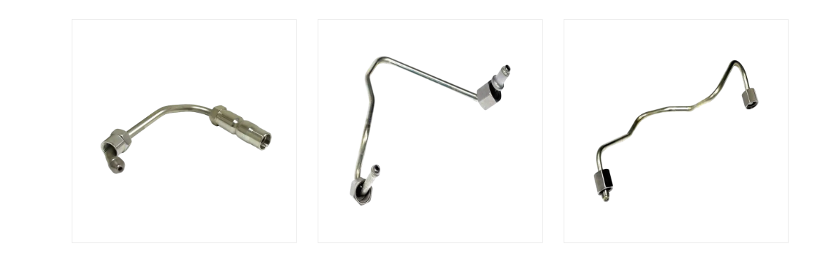
Common Rail High-Pressure Line
A rigid steel line connecting the common rail to an individual injector, built to withstand the very high, rapidly pulsing pressures used in modern diesel common rail systems.
Inline Pump Injector Line
An individual rigid steel pipe running directly from a mechanical inline injection pump to one injector, typical of older diesel engine designs without a common rail.
Corrugated Flexible Fuel Line
A flexible corrugated pipe generally used in lower-pressure supply or return circuits, where its ability to flex accommodates engine movement and vibration.
Custom CNC-Bent Replacement Line
A line bent to match a specific engine's three-dimensional routing, produced when a direct off-the-shelf replacement part is not available for an older or less common engine.
Low-Pressure Supply / Return Line
Carries fuel from the tank to the pump or routes excess fuel back to the tank, operating at far lower pressure than the injector-side high-pressure lines.
Fuel injector lines are engineered to withstand a very specific pressure envelope depending on the fuel injection system they serve. Older mechanical inline pump systems typically operate at meaningfully lower peak pressures than modern common rail systems. Diesel common rail architecture in particular has pushed injection pressures upward over successive engine generations to improve atomization and reduce emissions. Because the correct replacement line must be rated for at least the system's peak operating pressure, understanding where a given engine sits on this pressure spectrum is an important first step before ordering a replacement part. The gauge below illustrates an approximate position for modern diesel common rail systems within a general 0 to 250 MPa reference scale.
The gauge needle sits within the upper portion of the scale, reflecting the widely referenced point that modern diesel common rail systems commonly operate at peak pressures exceeding 200 MPa. This is meaningfully higher than the pressure range associated with older mechanical inline injection pump systems, which typically fall in the lower and middle portions of the same scale. The practical implication for anyone sourcing a replacement fuel injector line is straightforward: a line rated for an older, lower-pressure system should never be substituted onto a modern common rail engine, even if the physical dimensions appear similar. Manufacturers address this pressure requirement primarily through material selection and the cold-working process described in the next section, rather than simply by using a thicker wall on ordinary tubing. It is worth noting that the exact peak pressure for any specific engine model should always be confirmed against the engine manufacturer's own specification rather than assumed from a general reference scale like this one. Different engine generations from the same manufacturer can also operate at different pressure levels as emissions and performance requirements evolve over time. This is one reason fuel injector line replacement is not a one-size-fits-all task, and why matching the exact specification to the engine variant matters more than matching by rough physical appearance alone. For workshops handling a wide range of engine models, keeping a reference chart for common pressure ranges by system type can reduce the risk of installing an under-rated line. Because a line operating below its rated pressure envelope may fail without obvious warning signs beforehand, this specification check is generally treated as a safety-relevant step rather than an optional formality. Reviewing this pressure context also helps explain why fuel injector lines, unlike many other automotive pipe fittings, are manufactured to comparatively tight tolerances and dedicated pressure classes rather than a single universal design.
The correct fuel injector line must be rated for the specific pressure class of the engine it serves, since substituting a lower-pressure line onto a modern common rail system can lead to failure.
How Fuel Injector Lines Are Built: Material, Structure, and Working Principle
A fuel injector line is more than a simple length of tubing. It is typically made from specially selected high-strength, low-alloy steel tubing, then heat-treated to raise its base yield strength. Many high-pressure lines then go through an additional cold-working process known as autofrettage, in which the tube is subjected to controlled internal pressure that causes slight plastic deformation of the inner wall. Once that pressure is released, the inner wall retains a layer of residual compressive stress that must be overcome by operating pressure before any net tensile stress builds up in the material, which meaningfully improves fatigue resistance and burst pressure. Precision CNC tube-bending equipment is then used to shape the finished line to the exact three-dimensional geometry required by a specific engine, since a mismatched bend radius can concentrate stress at the wrong point along the line. The table below summarizes the structural elements typically found in a rigid high-pressure line compared with a flexible corrugated line.
Rigid High-Pressure Line Structure
|
Flexible Corrugated Line Structure
|
The fatigue resistance of a fuel injector line is determined largely by how the steel tubing is processed rather than by wall thickness alone. Repeated high-pressure pulses from each injection event place cyclic stress on the inner wall of the tube, which is where fatigue cracks are most likely to originate over time. Heat treatment can improve the base strength of the steel, but the further cold-working autofrettage process is specifically used to counteract this cyclic stress. The chart below presents an illustrative relative fatigue life index comparing standard tubing, heat-treated tubing, and autofrettage-treated tubing.
As the chart shows, standard steel tubing without additional processing is set as the baseline relative fatigue life index in this illustration. Heat-treated tubing shows a moderate improvement over the baseline, consistent with the general engineering principle that heat treatment increases base yield strength and therefore raises the stress level a tube can tolerate before fatigue damage accumulates. Autofrettage-treated tubing shows the largest improvement among the three categories in this illustrative comparison, which aligns with why this cold-working process is specifically associated with high-pressure fuel injector line manufacturing rather than general-purpose steel tubing. The mechanism behind this improvement is that residual compressive stress left in the inner wall after autofrettage must first be overcome by operating tensile stress before any net tensile stress develops, effectively raising the practical fatigue threshold. This is particularly relevant for injector lines because they experience a very high number of pressure cycles over an engine's operating life, making even a moderate improvement in fatigue resistance meaningful in cumulative terms. It is worth treating this chart as an illustrative relative comparison rather than a guarantee of a specific service life figure, since actual fatigue performance also depends on tube diameter, wall thickness, bend radius, and installation quality. A correctly manufactured and correctly installed autofrettage-treated line is generally expected to outperform a standard tube of similar dimensions under the same operating conditions, based on the underlying materials science described above. This is one of the reasons a specialized fuel injector pipe manufacturer typically treats this processing step as a core part of production rather than an optional upgrade. For buyers and workshops sourcing replacement lines, confirming that a supplier applies this kind of processing to high-pressure lines can be a relevant question, separate from the line's basic dimensional specification. Understanding this manufacturing detail also helps explain why a generic steel tube, even one with matching outer dimensions, is not considered an appropriate substitute for a purpose-built fuel injector line in a high-pressure application.
Autofrettage cold-working and precision CNC bending are what give a purpose-built fuel injector line its fatigue resistance, which is why a generic steel tube is not an appropriate substitute.
Application Scenarios and Key Selection Criteria for Fuel Injector Lines
Fuel injector lines are used across a wide range of diesel and direct-injection applications. Passenger and light-truck diesel engines with common rail systems rely on short, precisely bent high-pressure lines routed through a tightly packaged engine bay. Heavy-duty truck and agricultural diesel engines often use longer lines with more complex bend geometry to reach injectors positioned across a larger cylinder head. Marine diesel engines and industrial generator sets frequently use larger-diameter lines rated for continuous duty cycles rather than intermittent automotive use. Gasoline direct-injection systems also use dedicated high-pressure lines, though typically at lower peak pressures than diesel common rail systems.
When selecting or sourcing a replacement fuel injector line, buyers generally work through a consistent set of criteria before placing an order with a manufacturer or supplier:
- Does the line's pressure rating meet or exceed the engine system's peak operating pressure?
- Do the outer diameter and wall thickness match the original equipment specification?
- Does the bend geometry and overall length correctly reproduce the original routing?
- Do the end fittings and sealing cone angle match the pump and injector ports being connected?
- Is the tubing material and processing (heat treatment, autofrettage) consistent with high-pressure duty?
- Can the manufacturer or wholesaler support repeat orders with consistent dimensional accuracy for fleet or multi-unit needs?
Fuel injector lines do not experience a constant, steady pressure during engine operation; instead, pressure fluctuates rapidly as each injection event opens and closes the injector. This pulsation pattern repeats many times per second at typical engine speeds, placing repeated stress cycles on the line and its end fittings. Selecting a line rated only for the average operating pressure, rather than the peak pressure reached during each pulse, would leave a meaningfully reduced safety margin. Engineers reviewing injection system design typically look at pressure pulsation shape, not just a single peak number, to understand real operating conditions along the line. The area chart below presents an illustrative pressure pulsation pattern over one injection cycle for context.
The shaded area chart shows pressure rising sharply during the injection event itself, reflecting the brief period when fuel is being forced through the injector nozzle at peak system pressure. Outside of this injection window, pressure in the line settles toward a comparatively steadier baseline associated with the common rail or pump's holding pressure. This pattern repeats continuously while the engine runs, meaning the injector line experiences a very high number of these pressure cycles over normal operating hours. The practical significance of this pulsation pattern is that the line's rated pressure specification needs to account for the peak of each pulse, not simply an average pressure across the cycle. This is also part of why fatigue resistance, discussed in the previous section, is such an important design consideration for fuel injector lines specifically, since the line is essentially subjected to a continuous cyclic loading pattern rather than a single static pressure. Variations in engine speed and load also change the frequency, and to some extent the shape, of this pulsation pattern, since injection timing and duration adjust to match fueling requirements. A line correctly rated and processed for its intended pressure class is designed to tolerate this pulsation pattern over the engine's expected service interval. If a line has been under-specified or has developed fatigue damage from age or a manufacturing defect, this repeated pulsation is often the mechanism that eventually leads to a crack or failure at a stress concentration point such as a bend or fitting connection. This pulsation-driven stress pattern is also relevant to the earlier point about pressure rating: a line that appears adequate based on an average pressure figure alone may still be undersized relative to the actual peak pulse pressure it will experience in service. Recognizing this distinction is useful context when comparing specification sheets for different injector line options during a selection or replacement decision.
Choosing the right fuel injector line depends on matching pressure rating, dimensions, and bend geometry to the exact engine system, not just the general application category.
Fuel Injector Line Types: Detailed Comparison
The table below compares the three configurations most relevant to a replacement decision: the rigid high-pressure steel line, the flexible corrugated line, and a custom CNC-bent replacement line produced when an off-the-shelf part is unavailable.
| Dimension | Rigid High-Pressure Line | Flexible Corrugated Line | Custom CNC-Bent Line |
|---|---|---|---|
| Primary Use | Pump/rail-to-injector high-pressure delivery | Low-pressure supply/return circuits | Direct replacement for discontinued OEM lines |
| Typical Pressure Range | Often 100–250 MPa | Comparatively low pressure | Matched to original system rating |
| Material | Low-alloy steel, heat-treated, autofrettage-processed | Corrugated metal or reinforced flexible tubing | Same steel process as rigid line, custom-bent |
| Flexibility | Rigid, fixed geometry | Flexes to absorb vibration and movement | Rigid, produced to a specified geometry |
| Installation Precision Needed | High, exact bend and length match required | Moderate | High, must reproduce original routing |
| Typical Failure Point | Bend or fitting connection under fatigue | Corrugation wall or crimped fitting | Bend or fitting connection under fatigue |
Not every point along a fuel injector line experiences the same amount of stress during engine operation. Straight sections of tubing generally distribute pressure-related stress relatively evenly along their length. Bend sections, by contrast, concentrate additional stress at the outer radius of the curve, since the tube wall is thinner and geometrically more complex at a bend than along a straight run. Fitting connections introduce their own stress concentration due to the sealing cone geometry and the clamping force from the union nut. The heatmap below presents an illustrative relative stress index across these three pipe zones under three engine load conditions.
| Pipe Zone | Idle | Partial Load | Full Load |
|---|---|---|---|
| Straight Section | 2 | 4 | 6 |
| Bend Section | 3 | 6 | 9 |
| Fitting Connection | 3 | 5 | 8 |
The heatmap shows relative stress increasing from idle toward full load across all three pipe zones, which follows directly from the higher injection pressures and more frequent injection events associated with higher engine load. Within each load condition, the bend section consistently shows a higher relative stress index than the straight section, illustrating why bend geometry and bend radius are treated as important design details rather than incidental routing choices. Fitting connections also show elevated relative stress compared with straight sections, though generally somewhat lower than the bend section in this illustrative comparison, reflecting the concentrated but localized nature of stress at a threaded connection point. At full load, all three zones show their highest values in this illustrative pattern, consistent with the earlier discussion of pressure pulsation peaking during each injection event under higher fueling demand. This pattern helps explain why fatigue-related failures in fuel injector lines are more commonly reported at bend locations and fitting connections than along an undisturbed straight section of tube. For manufacturers, this is part of the justification for using precision CNC bending equipment that can produce a consistent, gradual bend radius rather than a sharp or uneven bend that would further concentrate stress at that point. For workshops performing a replacement, this pattern is also a practical reminder to inspect bend areas and fitting connections closely for any sign of surface damage, corrosion, or previous over-tightening before assuming a line is still serviceable. It further reinforces why a replacement line should reproduce the original bend geometry rather than using a sharper or tighter bend as a workaround during installation, since altering the bend radius can shift the stress concentration pattern shown here. Treating this heatmap as an illustrative engineering pattern rather than a measured result for any specific engine, workshops and equipment operators can still use the general zone-by-zone relationship to prioritize inspection points during routine maintenance.
Bend sections and fitting connections consistently carry more stress than straight sections, which is why replacement lines should reproduce the original bend geometry rather than a field-modified shortcut.
Replacement and Maintenance Guidance: How to Replace a Fuel Injector Line Safely
The following sequence outlines the general process for replacing a fuel injector line. Exact steps, torque values, and pressure-relief procedures should always be confirmed against the specific engine or equipment manufacturer's service documentation before starting work.
- Confirm the correct replacement line specification, including pressure rating, diameter, length, and bend geometry, against the OEM reference or service manual.
- Relieve residual fuel system pressure following the engine manufacturer's specified procedure before disconnecting any high-pressure line.
- Disconnect the battery or isolate the electrical system as a general precaution before working near the fuel system.
- Loosen and remove the union nuts at both the pump/rail end and the injector end using the correct size flare-nut or crow-foot wrench to avoid rounding the fittings.
- Carefully withdraw the old line without forcing it against adjacent components, noting its original routing and bend orientation.
- Inspect the sealing cone surfaces at both the injector and pump/rail ports for damage before installing the new line.
- Position the new line by hand first, aligning the sealing cones squarely before threading the union nuts to avoid cross-threading.
- Torque each union nut to the value specified by the engine or line manufacturer, avoiding both under-tightening and over-tightening.
- Reconnect the battery and follow the manufacturer's specified starting procedure to re-pressurize the fuel system.
- Start the engine at idle and visually check every new connection for fuel seepage before returning the vehicle or equipment to normal operation.
- Recheck the torque on each fitting after a short running period, since initial thermal cycling can sometimes require a follow-up check.
Sourcing a replacement line that matches the original equipment geometry is often the most difficult part of this process, particularly for older or less common engine models where an off-the-shelf line is not available. NINGBO JIATIAN AUTOMOBILE PIPE CO., LTD., established on the basis of the earlier Ningbo Xingxin Metal Products Factory founded in 1995, is a fuel injector line manufacturer and automotive pipe fitting factory located in Wanhou, Zhanqi Town, Yinzhou District, Ningbo, operating from a facility covering roughly 32,000 square meters with about 26,000 square meters of factory floor space. The company's production setup includes ten CNC fully automatic pipe bending machines, large-scale brazing furnace assembly lines, hydraulic internal forming equipment, an 800-ton hydraulic water expansion machine, automatic laser welders, welding robots, and large-scale machining centers, supported by an in-house research and testing laboratory. This kind of CNC bending and forming capability allows a fuel injector pipe supplier to reproduce a specific engine's three-dimensional routing accurately, which is directly relevant when a replacement line needs to match the original bend geometry rather than being adapted from a generic straight length. For fleet operators, workshops, and equipment manufacturers sourcing replacement lines in volume, working with an established automotive pipe manufacturer or wholesaler can help ensure consistent dimensional accuracy across repeat orders.
A safe fuel injector line replacement depends on relieving system pressure first, matching the exact original specification, and torquing every connection to the manufacturer's specified value.
Frequently Asked Questions About Fuel Injector Line Replacement
What is the correct procedure for replacing a fuel injector line?Replacing a fuel injector line generally involves confirming the correct replacement specification, relieving system pressure, removing the old line at both end fittings, inspecting the sealing surfaces, installing the new line by hand before torquing the union nuts to specification, and checking for leaks after restarting the engine. The exact sequence and torque values should always be confirmed against the specific engine or equipment manufacturer's procedure before starting work. |
Do I need to relieve fuel system pressure before removing an injector line?Yes, residual pressure can remain in a high-pressure fuel system even after the engine has been switched off, so following the manufacturer's specified pressure-relief procedure before disconnecting any injector line is a standard precaution. Skipping this step can create a safety risk given the pressures involved in common rail and similar high-pressure fuel systems. |
Can a fuel injector line be bent or reshaped during installation?Fuel injector lines are engineered and CNC-bent to a specific geometry, and reshaping or forcing a line during installation can introduce stress concentrations or surface damage that were not accounted for in the original design. If a replacement line does not match the required routing, sourcing a correctly bent replacement rather than field-modifying an existing line is generally the more reliable approach. |
What torque should be used when installing a new fuel injector line?Torque values for injector line union nuts vary by fitting size, thread type, and engine manufacturer specification, so the applicable service manual or manufacturer torque chart should be used for the exact figure rather than a general estimate. Both under-tightening and over-tightening can create reliability problems, which is why matching the specified torque value is treated as an important step in the replacement process. |
How do I know if a fuel injector line needs to be replaced rather than repaired?Visible cracking, corrosion, deformation, or fuel seepage around a bend or fitting connection are common indicators that a line should be replaced rather than repaired, since these lines operate under continuous high-pressure cycling that repair methods are generally not designed to withstand reliably. Any line showing damage near a stress concentration point such as a bend or fitting is typically treated as a replacement candidate rather than a repair candidate. |
What should a workshop or wholesaler look for when sourcing replacement fuel injector lines from a manufacturer?Buyers typically look at a manufacturer's ability to match the original bend geometry and pressure rating precisely, along with production capacity and consistency across repeat orders for fleet or multi-unit needs. Reviewing a supplier's manufacturing equipment and quality process, such as CNC bending accuracy and material traceability practices, can be a useful part of evaluating a fuel injector pipe manufacturer or wholesaler for ongoing sourcing. |
Replacing a fuel injector line safely comes down to matching the exact original specification and following the correct pressure-relief and torque procedure, rather than treating it as a generic tubing swap.
Our Main Products

 Contact Us
+86-138 0586 3066
+86-574 8840 6311
 Products
 Send An E-mail
 Mobile
Copyright ©NINGBO JIATIAN AUTOMOBILE PIPE CO.,LTD. All Rights Reserved.
 China's Premium Automotive Tube Factory
Custom Automotive Pipe Fittings Supply
privacy
China's Premium Automotive Tube Factory
Custom Automotive Pipe Fittings Supply
privacy