

 English
 Español
What Is a Fuel Injector Line? Function, Types and Applications Explained
Content
- 1 What Is a Fuel Injector Line
- 2 Core Functions of a Fuel Injection Pipe
- 3 Types of Fuel Injector Lines
- 4 Structure of a Fuel Injector Line
- 5 Fuel Injector Line Performance Data
- 6 Materials and Manufacturing Process
- 7 Applications of Fuel Injector Lines and Fuel Injection Pipes
- 8 Manufacturing Capability for Fuel Injector Lines
- 9 Installation and Maintenance Considerations
- 10 Frequently Asked Questions
- 10.1 Q1: What is a fuel injector line
- 10.2 Q2: What does a fuel injector pipe do
- 10.3 Q3: How does a diesel injector line work
- 10.4 Q4: What materials are fuel injector pipes made of
- 10.5 Q5: How often should fuel injector lines be inspected
- 10.6 Q6: Can a fuel injector line be repaired or should it be replaced
- 10.7 Q7: What causes a fuel injector line to leak or crack
- 10.8 Q8: Are fuel injector lines the same for gasoline and diesel engines
What Is a Fuel Injector Line
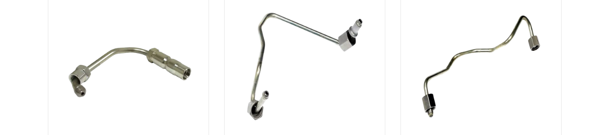
A fuel injector line, also referred to as a fuel injection pipe, is the rigid metal tube that carries pressurized fuel from the high pressure pump or the common rail to each fuel injector, maintaining the pressure and flow rate the combustion process requires. The pipe does not create pressure itself, it transmits pressure generated upstream while resisting expansion, vibration fatigue, and repeated pressure pulsation.
In modern diesel engines built around common rail or distributor pump architecture, this pipe operates under repeated pressure cycles that can exceed 2000 bar in current production systems, with some advanced platforms designed for pressures approaching 2700 bar. Because the line experiences these pressure surges many millions of times across a normal service interval, wall thickness, bend radius, and internal surface condition are engineered around fatigue life rather than a single burst pressure rating alone.
Core Characteristics
- Connects the high pressure pump or common rail directly to the injector body
- Transfers fuel treated as a non compressible fluid without measurable expansion
- Formed through CNC bending so tube geometry matches exact mounting points on the engine block
- Produced from cold worked steel tubing rated for repeated high pressure fatigue cycles
Core Functions of a Fuel Injection Pipe
A fuel injection pipe performs several jobs at the same time, and each one affects how an engine starts, idles, and responds under load.
Fuel Delivery
The primary job of the line is moving a metered fuel volume from the pump outlet to the injector inlet without loss, aeration, or delay, matching fuel injector line output to injector timing so every cylinder receives the same volume on schedule.
High Pressure Transmission
The pipe has to transmit pressure spikes generated by the pump or rail without expanding or absorbing energy that should instead reach the injector nozzle. Even a small amount of elastic expansion in the tube wall can delay pressure buildup at the injector tip, an effect engineers describe as volumetric efficiency loss.
Injection Timing Accuracy
Because fuel is treated as incompressible, pressure wave transfer through the line happens in a fraction of a millisecond. Any variation in pipe length, internal diameter, or wall stiffness between cylinders can shift injection timing slightly from one cylinder to another, so engineering teams specify matching fuel injector line lengths and bend paths across a cylinder bank wherever the layout allows it.
Support for Atomization
Stable pressure delivery at the injector nozzle is what allows fuel to atomize into the fine droplet pattern combustion requires. When a fuel injection pipe is worn, cracked, or undersized, pressure at the nozzle drops and atomization quality falls, which typically shows up as rough idle, harder cold starts, or increased exhaust smoke.
Types of Fuel Injector Lines
Fuel injector lines are generally grouped by wall structure and by the engine platform they are engineered to serve.
| Type | Structure | Typical Application |
|---|---|---|
| Single Wall Pipe | One continuous cold drawn steel wall | Passenger car and light duty diesel engines |
| Double Wall (Duplex) Pipe | Two layers cold formed into one wall for added burst margin | Heavy duty truck, bus, and off highway engines |
| Autofrettage Treated Pipe | Single wall pre stressed internally through controlled overpressure | Common rail systems above 2000 bar |
| Armored / Sleeved Pipe | Standard tube fitted with a protective outer sleeve at wear points | Engines with tight routing near moving components |
Classification by Application
- Passenger vehicle diesel fuel injector lines
- Light commercial vehicle fuel injection pipes
- Heavy truck and bus injector lines
- Agricultural and construction machinery lines
- Marine and industrial engine lines
- Generator set injector lines
Structure of a Fuel Injector Line
A finished fuel injector line assembly is built from more than a single tube. Each end is formed and machined to seal against the pump or rail on one side and the injector on the other, while the mid section is bent to a specific radius so it clears surrounding engine components without contact.
Simplified isometric view of a fuel injector line assembly between a pump or rail body and the injector
Key Components
- Cone seat: the machined tip that forms a metal to metal seal against the pump or rail outlet
- Union nut: threads onto the outlet stud and pulls the cone seat into sealing contact
- Tube body: the load bearing section between both ends, shaped through CNC bending
- Sleeve nut: the fitting on the injector side that secures the opposite end
- Protective sleeve: an optional outer layer added where the tube would otherwise rub against brackets or neighboring lines
Fuel Injector Line Performance Data
The figures below summarize commonly observed pressure ranges, dimensional distribution, and comparative performance across pipe types. They are presented as general reference points rather than specifications for any single engine model.
Injection Pressure Evolution Across System Generations
Approximate common rail pressure in bar across successive system generations
Typical Operating Pressure by Application
Typical upper operating pressure range by engine platform, expressed in bar
Common Outer Diameter Distribution
Relative share of outer diameter sizes commonly used across fuel injector line applications
Performance Comparison Across Pipe Types
Relative comparison of pipe types across five performance attributes, scored on a five point scale
Materials and Manufacturing Process
Material choice and forming method influence how long a fuel injector line holds up under repeated pressure cycling.
| Material | Typical Characteristic | Common Use |
|---|---|---|
| Carbon Steel | Cold drawn, high tensile strength, cost efficient | Passenger car and light duty applications |
| Alloy Steel | Higher fatigue resistance through alloying elements | Medium and heavy duty diesel systems |
| Stainless Steel | Strong corrosion resistance in humid or marine environments | Marine, industrial, and outdoor equipment engines |
Cold Forming and Autofrettage
By applying controlled internal pressure to the tube during processing, plastic deformation occurs at the inner wall, creating residual compressive stress. This residual stress offsets the tensile stress generated during normal operating pressure, which improves fatigue life and raises the burst pressure margin of the finished fuel injection pipe.
CNC Bending and Dimensional Control
CNC tube bending equipment shapes the three dimensional geometry of each fuel injector line so it matches the mounting points on a specific engine design, helping the finished part seat correctly without added stress at the connection points.
Applications of Fuel Injector Lines and Fuel Injection Pipes
Fuel injector lines are engineered around the routing space, duty cycle, and operating environment of the platform they serve.
- Passenger diesel cars: compact bend radii to fit short wheelbase engine bays
- Light commercial vans and pickups: lines matched to higher duty cycle idling and stop start use
- Medium and heavy duty trucks and buses: larger outer diameter lines rated for extended pressure cycling
- Agricultural and construction machinery: lines routed to tolerate dust, vibration, and wide temperature swings
- Marine and industrial engines: lines specified with added corrosion resistance for humid operating environments
- Generator sets and stationary power equipment: lines sized for continuous duty rather than variable load cycling
Manufacturing Capability for Fuel Injector Lines
Production facilities that operate as a fuel injector pipe manufacturer typically combine CNC tube bending, internal cold forming, and precision machining under one roof so that dimensional tolerances stay consistent from the first prototype through full production volume. A facility built around this scope commonly operates across tens of thousands of square meters and pairs automated tube bending centers with dedicated brazing and welding lines to keep OEM fuel injector line programs on a single, traceable production path.
Typical Production Equipment
- Multiple CNC fully automatic pipe bending machines for exact three dimensional geometry
- Hydraulic internal forming machines covering a wide diameter range
- Automated laser welding and welding robot cells for consistent joint quality
- Large scale machining centers for end forming, cone seats, and thread cutting
- A dedicated testing and inspection area for dimensional and pressure checks
Facilities set up this way are positioned to support both a diesel fuel injector pipe supplier relationship for aftermarket distribution and a common rail injector pipe manufacturer role for OEM platforms, since the same tube forming and autofrettage process line can switch between duplex, single wall, and armored configurations without separate tooling investment. For buyers researching a fuel injection pipe manufacturer China based supply chain, the combination of in house research and development, a controlled forming process, and integrated laboratory testing is generally what determines whether a high pressure fuel pipe supplier can hold tight tolerances across repeat production runs.
Installation and Maintenance Considerations
Correct handling before and after installation has a direct effect on how long a fuel injector line performs without issue.
Installation Practices
- Tighten union nuts following the torque sequence specified for the engine, working in even, gradual stages rather than one continuous pull
- Support the tube along its length with the original clamps so vibration load does not concentrate at the fitting ends
- Avoid re bending or straightening a formed line in the field, since reshaping a cold worked tube removes the residual stress pattern built in during manufacturing
Inspection and Wear Signs
- Fuel seepage or wet residue around the union nut area
- Visible surface cracking near the cone seat or at a bend apex
- Surface pitting or discoloration on lines exposed to moisture or road salt
- A rough idle or hard cold start that improves once rail pressure is checked
Storage Handling
When a fuel injector line is stored before installation, keeping the protective end caps in place and the tube in a dry, temperature stable area reduces the chance of moisture related surface corrosion before the part reaches the engine.
Frequently Asked Questions
Q1: What is a fuel injector line
A fuel injector line is a high pressure pipe that transfers fuel from the injection pump or common rail to the injector, maintaining the pressure needed for the injector to open and deliver fuel on schedule.
Q2: What does a fuel injector pipe do
It handles fuel delivery, high pressure transmission, and injection accuracy, keeping the pressure signal from the pump or rail consistent all the way to the injector nozzle.
Q3: How does a diesel injector line work
The line transmits fuel pressure with minimal delay, supporting precise injection timing and helping the injector produce a fine atomized spray pattern at the moment of injection.
Q4: What materials are fuel injector pipes made of
Common materials include stainless steel, carbon steel, and alloy steel, chosen based on pressure rating, fatigue requirements, and the operating environment of the engine.
Q5: How often should fuel injector lines be inspected
Routine visual inspection at each service interval is typical, checking for seepage at fittings, surface cracking near bends, and corrosion on the outer surface.
Q6: Can a fuel injector line be repaired or should it be replaced
Because the pipe relies on a specific internal residual stress pattern, a line showing cracking, deformation, or leakage is typically replaced rather than reshaped or repaired.
Q7: What causes a fuel injector line to leak or crack
Repeated pressure fatigue, loose or over tightened fittings, vibration chafing against nearby components, and corrosion are the most common causes.
Q8: Are fuel injector lines the same for gasoline and diesel engines
No, diesel common rail and pump systems generally operate at far higher pressures than gasoline direct injection systems, so line wall thickness and material selection differ accordingly.
Our Main Products

 Contact Us
+86-138 0586 3066
+86-574 8840 6311
 Products
 Send An E-mail
 Mobile
Copyright ©NINGBO JIATIAN AUTOMOBILE PIPE CO.,LTD. All Rights Reserved.
 China's Premium Automotive Tube Factory
Custom Automotive Pipe Fittings Supply
privacy
China's Premium Automotive Tube Factory
Custom Automotive Pipe Fittings Supply
privacy