

 English
 Español
Fuel Line Diagram: How to Read, Diagnose, and Replace Your Vehicle's Fuel Lines
Content
- 1 Why a Fuel Line Diagram Is a Practical Repair Tool
- 2 Core Components Shown on a Modern Fuel Line Diagram
- 3 How to Read a Fuel Line Diagram Step by Step
- 4 Supply Line vs. Return Line: Two Different Pressure Zones
- 5 Where Fuel Lines Fail First
- 6 Choosing a Replacement Fuel Line: Material and Fitment Checklist
- 7 Frequently Asked Questions About Fuel Lines and Diagrams
- 7.1 Q1: What is a fuel line diagram and why do I need one?
- 7.2 Q2: What is the difference between a fuel supply line and a fuel return line?
- 7.3 Q3: Can I replace a metal fuel line with rubber fuel hose?
- 7.4 Q4: How often should fuel lines be inspected?
- 7.5 Q5: Why does my car show two fuel lines on the diagram but only one under the hood?
- 7.6 Q6: What does the fuel pressure regulator do on the return line?
You catch a whiff of fuel in the garage, or you spot a dark stain on the driveway under the engine bay. The natural response is to open the hood and trace the source—only to find several pipes running in different directions, all looking similar. The engine bay does not come with labels, and without a fuel line diagram, identifying the supply line, return line, and vapor line becomes guesswork. That guesswork is exactly what leads to wrong parts, leaking fittings, and repeat repairs.
This guide explains how to read a fuel line diagram, what each line actually does, where failures most often occur, and what to check before buying a replacement fuel line.
Why a Fuel Line Diagram Is a Practical Repair Tool
A fuel line diagram is more than a service manual illustration. On a modern vehicle, the fuel delivery system is split into at least two pressure zones: a pressurized feed circuit from the tank to the injectors, and a low-pressure return or vapor circuit back to the tank. Some vehicles are returnless, which means an extra internal line runs inside the fuel pump module instead of a visible return pipe.
Misidentifying one line can create low fuel pressure, hot-start issues, or an invisible leak that becomes a fire risk. The diagram is the shortest route between identifying a damaged pipe and fixing the right one. Without it, you are guessing on a system where a wrong guess is expensive and potentially dangerous.
Core Components Shown on a Modern Fuel Line Diagram
Every factory fuel line diagram is built around the same basic architecture, even if the routing differs between makes. The components below appear in nearly every non-CNG passenger vehicle.
| Component | Location in the circuit | Primary function |
|---|---|---|
| Fuel tank | Rear of vehicle | Stores fuel and houses the pump module |
| Fuel pump module | Inside tank | Draws fuel and pressurizes the system |
| Fuel filter | Along feed line, before rail | Removes particles and water |
| Fuel supply line | Tank to engine bay | Delivers pressurized fuel forward |
| Fuel rail | On intake manifold | Distributes fuel to all injectors |
| Fuel return line | Rail to tank | Routes excess fuel back |
| EVAP vapor tube | Tank to carbon canister | Captures fuel vapor for emissions control |
On returnless systems, the diagram may show only a supply line at the engine bay, with the return function handled by the pressure regulator inside the tank. The EVAP vapor tube is still present on the drawing, so do not mistake it for a fuel return line when you are tracing pipes.
How to Read a Fuel Line Diagram Step by Step
Reading a fuel line diagram is about following flow, not just tracing lines. Start at the tank and move forward; the drawing will always show the pump somewhere between the tank and the filter. Focus first on arrows and part numbers, then on physical details such as thread type, quick-connect size, and bracket position.
- Read the legend and note the stated fuel pressure value and any abbreviations used for fittings.
- Find the fuel pump module inside the tank and confirm whether the system has a visible return line or is returnless.
- Trace the supply line from the pump to the filter, then to the fuel rail, checking clips and heat shields along the path.
- Identify the return path: a separate pipe back to the tank on older designs, or an internal circuit inside the pump module on newer ones.
- Compare part numbers against the diagram before removing anything, because a one-digit difference in an OE number can change the bend angle.
In practice, the most useful habit is to photograph the diagram and then match each physical line to its drawing by color, diameter, and connector shape before loosening any clamp.
Supply Line vs. Return Line: Two Different Pressure Zones
On a typical port-injected engine, the supply line carries fuel at 45–65 psi (about 3.1–4.5 bar) from the pump to the fuel rail. The return line operates at near-atmospheric pressure after the fuel pressure regulator. The diagram makes this distinction visible because the supply line is usually drawn thicker and labeled with a pressure spec, while the return line is thinner and unlabeled.
| Characteristic | Supply line | Return line | Vapor/EVAP line |
|---|---|---|---|
| Working pressure | 45–65 psi (typical port injection) | 0–5 psi after regulator | Vacuum / low pressure |
| Flow direction | Tank → filter → fuel rail | Fuel rail → tank | Tank → canister → intake |
| Common material | Steel, nylon, or PTFE hose | Nylon or rubber hose | Nylon or plastic tube |
| Typical failure mode | Rust at steel clamps, cracked fittings | Softening, abrasion, dry rot | Brittle cracking at connectors |
On a returnless system, the fuel pressure regulator sits inside the fuel pump module, so the diagram will not show a return line going to the engine. Instead, the excess fuel cycles through a short internal line inside the tank. Knowing this before you start prevents you from buying a return line that your car never had.
Where Fuel Lines Fail First
Fuel line diagrams are also failure maps. In shop practice, fuel leaks cluster at a handful of predictable points, and most of them are visible if you know where to look.
- Quick-connect fittings that crack or lose o-ring seal tension after heat cycles.
- Steel sections under the chassis that corrode from the outside after exposure to road salt and moisture.
- Coupling joints where the rubber liner has aged and hardened, causing a weep at the clamp.
- Sections in contact with sharp brackets, heat shields, or wiring harnesses that abrade the outer layer.
- Areas where the line was bent too sharply during an earlier repair, restricting flow and stressing the material.
Most of these issues come down to correct routing and clean fitting preparation. The article on preventing leaks in automotive pipe fittings covers the practical details of pipe-end prep, clamp torque, and fitting alignment that keep a new fuel line leak-free for years.
Choosing a Replacement Fuel Line: Material and Fitment Checklist
Choosing a replacement fuel line means matching both material and geometry. Rubber hose is flexible but degrades more quickly with ethanol-blended fuel. Nylon tubing resists fuel and is light, but it cannot tolerate the heat near an exhaust manifold. Stainless steel and PTFE braided hose are the most durable options for high-pressure or high-heat locations. The bar chart below compares typical working pressures for common fuel-line materials; treat it as orientation, not as a substitute for the rating printed on the product you buy.
Once the material is correct, geometry matters just as much. A direct-fit replacement supply line is worth choosing not because the metal is exotic, but because the bend radius, connector length, and bracket positions are already validated by the original design. Attempting to hand-bend a metal line often produces a kink that restricts fuel flow, and matching the factory routing points from the diagram is the reliable path.
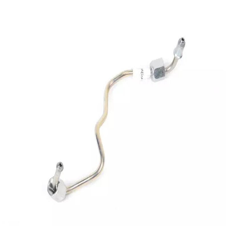
 Fuel Supply Line for Reliable Fuel DeliveryThis fuel supply line is designed to withstand corrosive fuels and high engine-bay temperatures, ensuring stable pressure from tank to injectors. Its precision-fit geometry matches factory routing, reducing kink risks and supporting long-term durability.View Product →
The same logic applies to the last section before the injectors. A worn or kinked injector feed pipe shows up as a lean cylinder and rough idle long before it develops a visible leak, which is why choosing the right fuel injector pipe for your engine is a decision about flow and vibration fatigue, not just connection size. A precision-made injector feed line keeps the pressure stable under the pulsing load of the injectors.
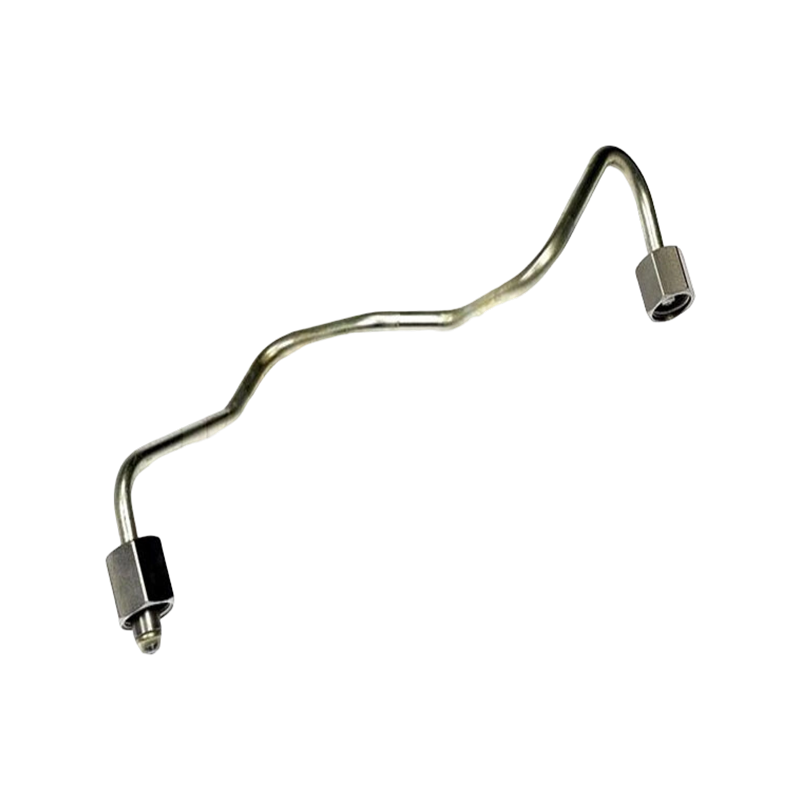
 Precision Fuel Injector Line (OE# 98063063)A direct-fit replacement for OE# 98063063, this high-pressure line uses certified CuNiFe material to prevent internal corrosion and leaks. It restores precise diesel delivery and engine performance, with technical support and sample shipping available.View Product →
The line chart below shows how fuel pressure changes along a typical port-injection circuit. This is not just a reading exercise: it explains why the supply section needs metal or reinforced hose, while the short return section can use a plain rubber hose rated for a much lower pressure.
Finally, an isometric view is the most useful for understanding how the fuel line diagram relates to the actual vehicle. The simplified drawing below places the tank at the rear, the rail at the front, and the supply line running along the outside of the underbody while the return line takes a softer path closer to the center. Keep that spatial relationship in mind, and identifying lines under the car becomes much easier.
Frequently Asked Questions About Fuel Lines and Diagrams
Short answers to the questions that come up most often in repair bays and customer calls.
Q1: What is a fuel line diagram and why do I need one?
A fuel line diagram is a service drawing that shows the exact routing of all fuel-related pipes from the tank to the engine. You need one whenever replacing a hose, diagnosing a leak, or planning a fuel system service, because it removes guesswork about which line connects where.
Q2: What is the difference between a fuel supply line and a fuel return line?
The supply line carries pressurized fuel from the pump to the injectors, usually at 45–65 psi on port-injection engines. The return line routes excess fuel back to the tank at much lower pressure. Returnless systems do not have a conventional return line at the engine.
Q3: Can I replace a metal fuel line with rubber fuel hose?
You can, as long as the hose is rated for fuel injection pressure and for the fuel type you use. But rubber does not hold its shape, so it must be routed away from heat and moving parts, and secured at shorter intervals than a steel tube needs.
Q4: How often should fuel lines be inspected?
Many manufacturers schedule a visual fuel-line inspection at major service intervals around 60,000 miles (96,000 km) or five to six years. If you run ethanol-blended fuel, inspect rubber sections more often because ethanol accelerates rubber degradation.
Q5: Why does my car show two fuel lines on the diagram but only one under the hood?
Many returnless vehicles show a second internal line inside the fuel pump module on the diagram, plus a vapor/EVAP line running to the carbon canister. Only the supply line actually reaches the engine compartment.
Q6: What does the fuel pressure regulator do on the return line?
The regulator keeps rail pressure constant by bleeding excess fuel back to the tank. On the diagram it is usually drawn near the fuel rail or inside the pump module; a failed regulator shows up as pressure that rises quickly at idle.
Our Main Products

 Contact Us
+86-138 0586 3066
+86-574 8840 6311
 Products
 Send An E-mail
 Mobile
Copyright ©NINGBO JIATIAN AUTOMOBILE PIPE CO.,LTD. All Rights Reserved.
 China's Premium Automotive Tube Factory
Custom Automotive Pipe Fittings Supply
privacy
China's Premium Automotive Tube Factory
Custom Automotive Pipe Fittings Supply
privacy